Circuit Representation
Table of Contents
When we build and design circuits, we use various tools (such as notation, units, symbols, and more) to come up with a circuit representation. This begins with creating a block diagram, which is a high-level overview of what the circuit accomplishes, then a schematic, which designs the circuits to do this, then a layout, which describes how the physical components are to be placed to make the circuits, and finally an assembly, which assembles the layout into a physical circuit (often a printed circuit board or PCB).
1. Notation
1.1. Units
Here are some common units° that are used in circuits:
| Dimension | Unit | Symbol |
|---|---|---|
| Charge | coulomb | \(\text{C}\) |
| Voltage | volt | \(\text{V}\) |
| Current | amp | \(\text{A}\) |
| Resistance | ohm | \(\Omega\) |
| Capacitance | farad | \(\text{F}\) |
| Inductance | henry | \(\text{H}\) |
| Power | watt | \(\text{W}\) |
| Frequency | hertz | \(\text{Hz}\) |
Prefixes are also used to denote multiples and submultiples of units:
| Prefix | Symbol | Magnitude |
|---|---|---|
| peta | \(\text{P}\) | \(10^{15}\) |
| tera | \(\text{T}\) | \(10^{12}\) |
| giga | \(\text{G}\) | \(10^9\) |
| mega | \(\text{M}\) | \(10^6\) |
| kilo | \(\text{k}\) | \(10^3\) |
| milli | \(\text{m}\) | \(10^{-3}\) |
| micro | \(\mu\) | \(10^{-6}\) |
| nano | \(\text{n}\) | \(10^{-9}\) |
| pico | \(\text{p}\) | \(10^{-12}\) |
| femta | \(\text{f}\) | \(10^{-15}\) |
1.2. Typeset
Symbols with lowercase and uppercase generally have the following meanings:
- A lowercase letter represents the general case (e.g. \(i\), current, may or may not be time-varying)
- A lowercase letter followed by \((t)\) to emphasize time (e.g. \(i(t)\) is time-varying current)
- An uppercase letter if the quantity is not time-varying (e.g. \(I\) is current of a constant value)
2. Architecture
2.1. Components
Circuits are created using components, which are represented on schematics using abstracted symbols:
| Component | Description | Symbol |
|---|---|---|
| Resistor (R) | US style | |
| Resistor (R) | EU style | |
| Capacitor (C) | Non-polarized | |
| Capacitor (C) | Polarized | |
| Capacitor (C) | Polarized (electrolytic) | |
| Inductor (L) | Coil | |
| DC Source | Battery/voltage source | |
| AC Source | Sinusoidal source | |
| LED | Light emitting diode | |
| Switch | SPST (single throw) |
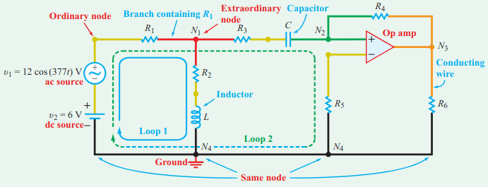
2.2. Terminology
The following is a diagram of the terminology used in a schematic:
2.3. Sources
2.3.1. Independent Source
An independent voltage source provides a pre-specified voltage at its two terminals, independent of the load that it sees (i.e. independent of the current that it has to provide in the circuit).
An independent current source provides a pre-specified current through itself, independent of the voltage applied across its two terminals.
2.3.2. Dependent Source
Dependent sources depend on the voltage or current in another part of the circuit. There are several types of dependent sources:
2.3.3. Ideal vs. Non-Ideal
3. Sign Conventions
When current enters the negative terminal of a device and exits through the positive terminal, then the device is a supplier of power, with a negative voltage drop (voltage rises).
When current enters the positive terminal of a device and exits through the negative terminal, then the device is a recipient of power, with a positive voltage drop.